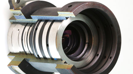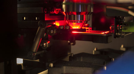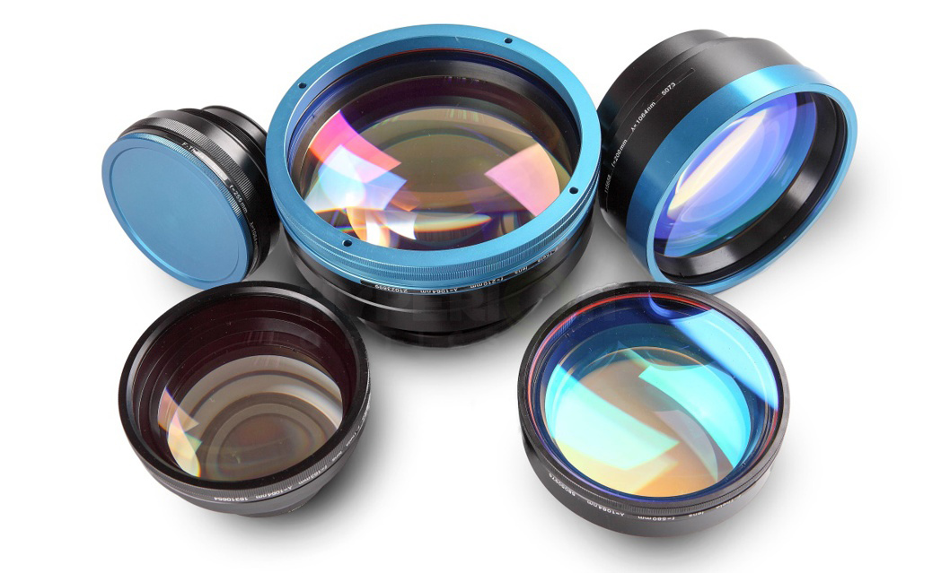
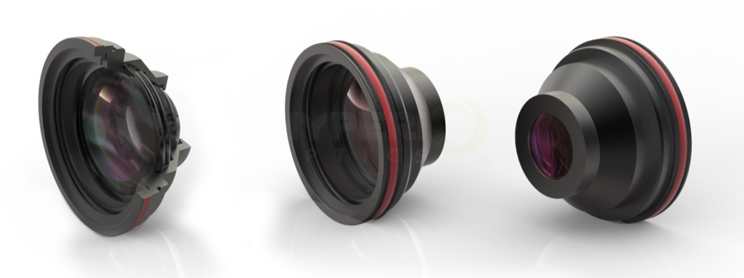
The F-Theta scanning lenses are commonly used in laser scanning systems that employ two-axis galvanometers to scan a specified area but cannot tolerate the angle at the image plane. By introducing a specified amount of barrel distortion in a scanning lens, the F-Theta scanning lens becomes an ideal choice for applications that require a flat field on the image plane such as laser scanning, marking, engraving and cutting systems. Depending on the requirements of the application, these diffraction limited lens systems can be optimized to account for wavelength, spot size, and focal length, and distortion is held to less than 0.25% throughout the field of view of the lens.
| Part No. | Scan Field | Input Beam | Focus Spot | Max. Scan Angle | Thread | M1-M2 | WD | Window | |
| EFL (mm) | Ф(1/e2) | Ф(1/e2) | (±deg) | (mm) | (mm) | Dia×Thk | |||
| (mm) | (mm) | (μm) | (mm) | ||||||
| HYP-1064-50-100Q | 100 | 50x50 | 15 | 13 | 21.3 | M85x1 | 25.6 | 131 | 94x2.5 |
| HYP-1064-94-163Q | 163 | 94x94 | 20 | 23 | 24.7 | M85x1 | 26 | 204.8 | 138x2.5 |
| HYP-1064-112-163Q | 163 | 112x112 | 10 | 30 | 25 | M85x1 | 12.5 | 203.7 | 120x2.5 |
| HYP-1064-170-255Q-D20 | 255 | 170x170 | 20 | 24 | 28 | M85x1 | 25.8 | 319.4 | 150x3 |
| HYP-1064-142-277Q | 277 | 142x142 | 15 | 32.5 | 21 | M85x1 | 26 | 347.5 | 96x2.5 |
| HYP-1064-215-340Q-D20 | 340 | 215x215 | 20 | 32 | 25 | M85x1 | 27 | 203.8 | 140x3.5 |
| HYP-1064-220-460Q-D30 | 460 | 220x220 | 30 | 44 | 25 | M98x1 | 43 | 572.4 | 144x4 |
| HYP-1064-280-420Q | 420 | 280x280 | 14 | 60.7 | 27 | M85x1 | 17 | 506.3 | 112x2.5 |
| HYP-1064-320-450Q | 450 | 320x320 | 14 | 45 | 25 | M85x1 | 15 | 515.9 | 104x3.9 |
| HYP-1064-280-500Q-D30 | 500 | 280x280 | 30 | 34 | 22.9 | M85x1 | 37 | 618.3 | 180x3.5 |
| HYP-1064-340-500Q-D20 | 500 | 340x340 | 20 | 14.5 | 26.8 | M85x1 | 26 | 569.8 | 140x3.5 |
| HYP-1064-350-640Q | 640 | 350x350 | 10 | 95.7 | 23.6 | M85x1 | 16 | 706.9 | 73x2.5 |
| HYP-1064-425-875Q-D20 | 875 | 425x425 | 20 | 93.2 | 19.3 | M85x1 | 26 | 975.2 | 83x2.5 |
| Part No. | Scan Field | Input Beam | Focus Spot | Max. Scan Angle | Thread | M1-M2 | WD | Window | |
| EFL (mm) | Ф(1/e2) | Ф(1/e2) | (±deg) | (mm) | (mm) | Dia×Thk | |||
| (mm) | (mm) | (μm) | (mm) | ||||||
| HYP-980-160-260Q-D20 | 260 | 160x160 | 20 | 30 | 23 | M85x1 | 27 | 130 | 138x2.5 |
| HYP-980-215-335Q-D20 | 335 | 215x215 | 20 | 35 | 24 | M85x1 | 27 | 200 | 140x3.5 |
| HYP-980-280-420Q | 418.5 | 280x280 | 14 | 56.1 | 27.1 | M85x1 | 17 | 497.3 | 112x2.5 |
| HYP-980-400-640Q-D20 | 640 | 400x400 | 20 | 64 | 24.5 | M85x1 | 27 | 556 | 128x3.5 |
| HYP-980-450-650Q-D30 | 650.0 | 450x450 | 30 | 103 | 25 | M123x1 | 37 | 784.9 | 220x5 |
| Part No. | Scan Field | Input Beam | Focus Spot | Max. Scan Angle | Thread | M1-M2 | WD | Window | |
| EFL (mm) | Ф(1/e2) | Ф(1/e2) | (±deg) | (mm) | (mm) | Dia×Thk | |||
| (mm) | (mm) | (μm) | (mm) | ||||||
| HYP-1940-635-60-163 | 163 | 60x60 | 14 | 29 | 25 | M85x1 | 18 | 128.2 | 68x2.5 |
| Part No. | Scan Field | Input Beam | Focus Spot | Max. Scan Angle | Thread | M1-M2 | WD | Window | |
| EFL (mm) | Ф(1/e2) | Ф(1/e2) | (±deg) | (mm) | (mm) | Dia×Thk | |||
| (mm) | (mm) | (μm) | (mm) | ||||||
| HYP-1064-635-100-163 | 163 | 100x100 | 12 | 22.5 | 25.5 | M85x1 | 20 | 157.6 | 85x2 |
| HYP-1064-635-180-260 | 260 | 180x180 | 15 | 28 | 28.3 | M85x1 | 20 | 261.4 | 123x3 |
| HYP-1064-630-150-254B | 254 | 150x150 | 30 | 110 | 25 | M102X1 | 43 | 306.9 | 128x4 |
| HYP-1064-532-100-163 | 163 | 100x100 | 12 | 21 | 25 | M85x1 | 14 | 159.7 | 84x2 |
| HYP-1064-532-175-254 | 254 | 175x175 | 15 | 25 | 28 | M85x1 | 16 | 262.8 | 120x3 |
| Part No. | Scan Field | Input Beam | Focus Spot | Max. Scan Angle | Thread | M1-M2 | WD | Window | |
| EFL (mm) | Ф(1/e2) | Ф(1/e2) | (±deg) | (mm) | (mm) | Dia×Thk | |||
| (mm) | (mm) | (μm) | (mm) | ||||||
| HYP-532-635-100-163 | 163 | 100x100 | 10 | 12.4 | 24.8 | M85x1 | 13 | 121 | 97x2.5 |
| Part No. | Scan Field | Input Beam | Focus Spot | Max. Scan Angle | Thread | M1-M2 | WD | Window | |
| EFL (mm) | Ф(1/e2) | Ф(1/e2) | (±deg) | (mm) | (mm) | Dia×Thk | |||
| (mm) | (mm) | (μm) | (mm) | ||||||
| HYP-1030-950-200-400 | 400 | 200x200 | 30 | 26.4 | 20 | M85x1 | 36 | 390.2 | 120x3.5 |
| Part No. | Scan Field | Input Beam | Focus Spot | Max. Scan Angle | Thread | M1-M2 | WD | Window | |
| EFL (mm) | Ф(1/e2) | Ф(1/e2) | (±deg) | (mm) | (mm) | Dia×Thk | |||
| (mm) | (mm) | (μm) | (mm) | ||||||
| HYP-355-635-90-170 | 170 | 90x90 | 10 | 14 | 21.5 | M85x1 | 20 | 116.1 | 95x2.5 |
| HYP-355-635-110-220 | 220 | 110x110 | 10 | 11.5 | 20.2 | M85x1 | 13 | 166.3 | 90x3 |
| HYP-355-635-212-328 | 328 | 212x212 | 6 | 45 | 17.9 | M85x1 | 13 | 265.2 | 104x3 |
| Part No. | Scan Field | Input Beam | Focus Spot | Max. Scan Angle | Thread | M1-M2 | WD | Window | |
| EFL (mm) | Ф(1/e2) | Ф(1/e2) | (±deg) | (mm) | (mm) | Dia×Thk | |||
| (mm) | (mm) | (μm) | (mm) | ||||||
| HYP-355-532-90-170 | 170 | 90x90 | 10 | 13.1 | 21.5 | M85x1 | 20 | 125.6 | 95x2.5 |
| Part No. | Scan Field | Input Beam | Focus Spot | Max. Scan Angle | Thread | M1-M2 | WD | Window | |
| EFL (mm) | Ф(1/e2) | Ф(1/e2) | (±deg) | (mm) | (mm) | Dia×Thk | |||
| (mm) | (mm) | (μm) | (mm) | ||||||
| HYP-355-405-110-178 | 178 | 110x110 | 10 | 15 | 24.7 | M85x1 | 13 | 92.4 | 106x3 |
In addition to these standard designs, we can develop complete systems for you, use components from laser beam shaping to the expansion and splitting of laser beams.
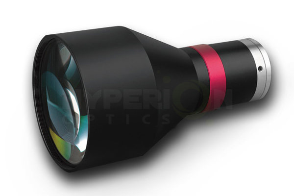
F-theta Lenses can shoot and form the image of objects of limited distance. It provides full glass high-performance lens, and different lenses meet the functions of A3, A4, barcode scanning. It is applied to the flatbed scanner and high shot instrument equipment. The lens is close to the diffraction limit and has small distortion, which meets the requirements of use.
To change the directions of beams through moving the scanner. To make the movement become the one of the focus on the focal plane by focus lens’s focusing. Laser scanning can be divided into pre-objective scanning and scanning after the objective lens. Usually scanning device with the high requirement is pre—objective scanning.
1. Scanning objective belongs to the imaging difference system with a small aperture, which requires rather high optical resolution.
2.Because of a photoelectric device, it should not only adjust the aberration of white light (mixed light), but consider aberrations of three independent wavelengths of R, G and B.
3. To correct the distortion aberration.
 Call us on:
  Email us:
  9B-4F, No.1 Qingnian Road Liando U Valley,Yuhua International Wisdom Valley, Nanjing, 210039 China


 English
  cn
cn  de
de  es
es  fr
fr 
